Which tripod should I use with the
a Static GPS/GNSS Receiver?
This is an EXCELLENT question.
Long OPUS-Static occupations will
generate very accurate and repeatable horizontal and vertical
positions. OPUS-Project occupations will do even better. It is
important to hold extremely tight leveling procedures and HI
measurements.
It is strongly recommend that you use:
(1.) A fixed
height tripod, and if you have more than one receiver then all
tripods should be the same height.
(2.) A tripod
that allows you to check the bubble in the field, immediately
prior to every occupation.
(3.) A tripod
that allows you to rotate the X90-OPUS head so the pushbuttons
are facing North.
Why?
When you run an OPUS occupation there
are only a few things that you can do to mess it up. A bad HI
(Instrument Height above the survey mark) is the most common
problem. Choosing the wrong antenna type is another, but our
download tool fills in the value for you automatically so that won't
be an issue.
(1.) If you ONLY use
2-meter fixed height tripods or poles, then you can just set the
default HI to 2-meters and never mess with it. There will never be a
question of an occupation's height, the answer will ALWAYS be 2.000
meters.
We sell some absolutely fantastic fixed
height tripods. The
SECO 5119-00 is the top-of-the-line. But they sell for nearly
$815 list! That is 1/3 the cost of an X90-OPUS receiver!
For this reason, our favorite
inexpensive solution is a 2-meter SECO range pole
PN 5125-00 (
pdf ). This pole unscrews into two pieces in the center and has
virtually no run-out1. (A SECO
PN 5125-20 snap-loc pole is decent, however they all have 3 to 5
mm of run-out.)
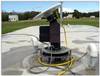
We use a 'Hold-A-Pole' (and we include
a 'Hold-A-Pole' in the box with every X90-OPUS receiver):

It has the advantage of fixed height,
the ability to quickly check your bubble prior to EVERY shot, allows
the receiver and pole to rotate 360 degrees and leverages the weight
and availability of your existing tripods.
The combination is relatively cow-proof
too!
Rod and
Pole Lengths
This is
Important: If you have a 2-meter pole or tripod, don't
just assume that it really is 2.000 meters! The point could be
worn or the pole could be slightly short or long. It is best to take
a few moments in your shop to verify exact pole length and shim or
file if required. If you are using a split pole, don't interchange
top and bottoms from two different poles as they may not be exactly
the same length.
One of the best discussions I have seen
is Robert Reese's articles in the California Surveyor's publication.
See page 26 in both these issues:
http://www.californiasurveyors.org/calsurveyor/CalSurv148.pdf
http://www.californiasurveyors.org/calsurveyor/CalSurv149.pdf
Even with brand new poles and points,
it may still be necessary to shim or file a point to make a pole the
perfect-length.
Obviously the freedom to pick any pole
in your quiver and have the same HI (2.000) every time is worth any
effort!
Checking
Bubble Adjustment
(2.) Before each use,
with a 'Hold-A-Pole', you can move the pole bubble to the right and
center the bubble. Now rotate the bubble 180 degrees to the left,
the bubble should remain exactly centered, if it is not adjust the
bubble 1/2 way back to the center and repeat.
Keeping your poles in a padded case
and treating them like an expensive rifle scope will serve you
well! Just like a rifle scope, if you drop a pole, you HAVE TO
check the bubble before the next shot.
Rotating
the Receiver to North
(3.) If the world
were perfect, the ground plane and antenna in the X90-OPUS would be
EXACTLY centered to a tenth of a millimeter above the center of the
rod.
The world is not perfect.
So we do everything we can to make
every X90-OPUS exactly the same, then we model the eccentricy of the
GPS head by measuring sample heads on a jig.
In addition to phase center eccentricy,
there is also a change in apparent antenna phase center with the
elevation of satellites above the horizon.
The results can be seen on the NGS
website [
here ] and below. The L1 horizontal centering error is
highlighted below:
CHCX90D-OPUS    NONE P/N:1190403181, X90 L1/L2/L2C      MMI-> NGS (  2) 13/03/19
       1.1      -0.7      89.3
   0.0  -0.1  -0.3  -0.5  -0.8  -1.3  -1.7  -2.1  -2.4  -2.5
  -2.6  -2.6  -2.6  -2.5  -2.2  -1.7  -0.7   0.0   0.0
       0.7      -3.1     101.7
   0.0  -0.9  -1.6  -2.2  -2.4  -2.7  -2.9  -3.2  -3.4  -3.6
  -3.8  -3.8  -3.7  -3.6  -3.6  -3.8  -3.8   0.0   0.0
The X90-OPUS has excellent
centering, not
perfect but on the order of 1-millimeter. (All the measurements
above are millimeters.) The NGS OPUS processor knows about this
error (if we choose the correct antenna type when submitting a job) and compensates for
the centering error assuming that the MMI (Man-Machine-Interface or
pushbuttons) are pointed to the North when you make an observation.
If you rotate the GPS head so that the
MMI faces south, then the NGS OPUS processor will double the
centering error! That's not so good...
Conclusion
By diligently recording HI (or making
it the same every single time); checking the bubble on every shot;
routinely checking the pole height and always rotating the head to
North you can minimize the chance for error and maximize the
accuracy of your OPUS solutions.
---
1Run-out:
if the pole is not straight, when you turn the pole in a jig the top
will move from side to side; the deviation in one revolution, when
held at the bottom point and pole center is the run-out.
|